
Release Notes - [04/10/2026]
![Release Notes - [04/10/2026]](https://mintcdn.com/mi4/4JNwR2i_Dp9jNaBb/images/wbd.png?fit=max&auto=format&n=4JNwR2i_Dp9jNaBb&q=85&s=25ab541949a7476a844739f62f37928b)
- Wellbore Diagrams
Wellbore Diagrams
Create New Wellbore Diagram
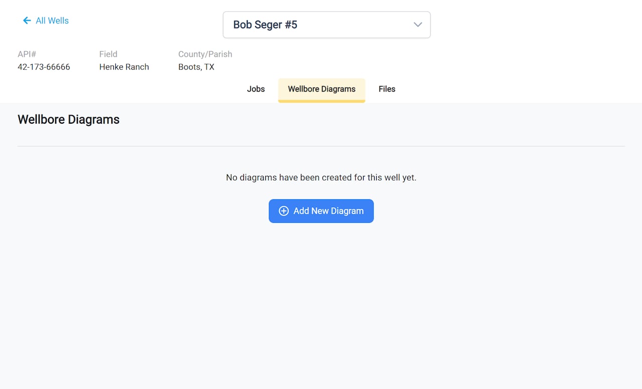
Click Add New Diagram from Well page
Choose the Data Source
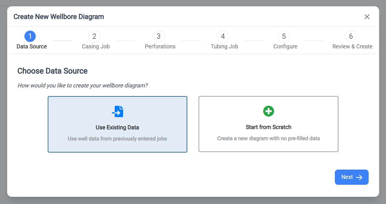
- Use Existing Data - Import casing, tubing, and perforation data from jobs already entered in RigReports. The system will automatically detect available jobs for this well.
- Start from Scratch - Enter all component information manually in the editor.
Select the Casing Job
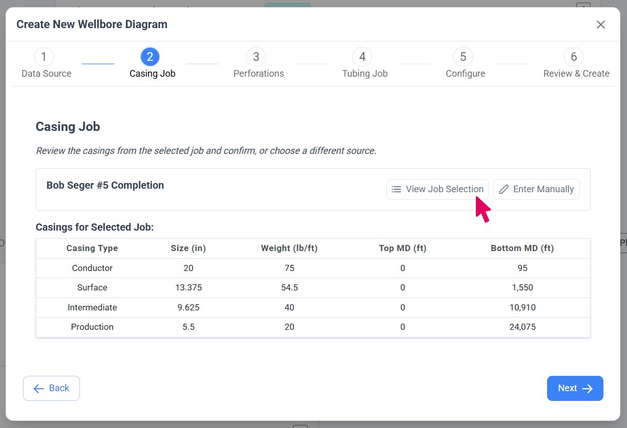
- View Job Selection - Click this button to open a table showing all available jobs with casing data for this well. In the table, you can click Show next to any job to preview the casings associated with that job, or click Select to choose a job to import casings from.
- Enter Manually - Click this button if you prefer to skip importing casing data and enter it manually in the editor instead.
Select the Perforation Job
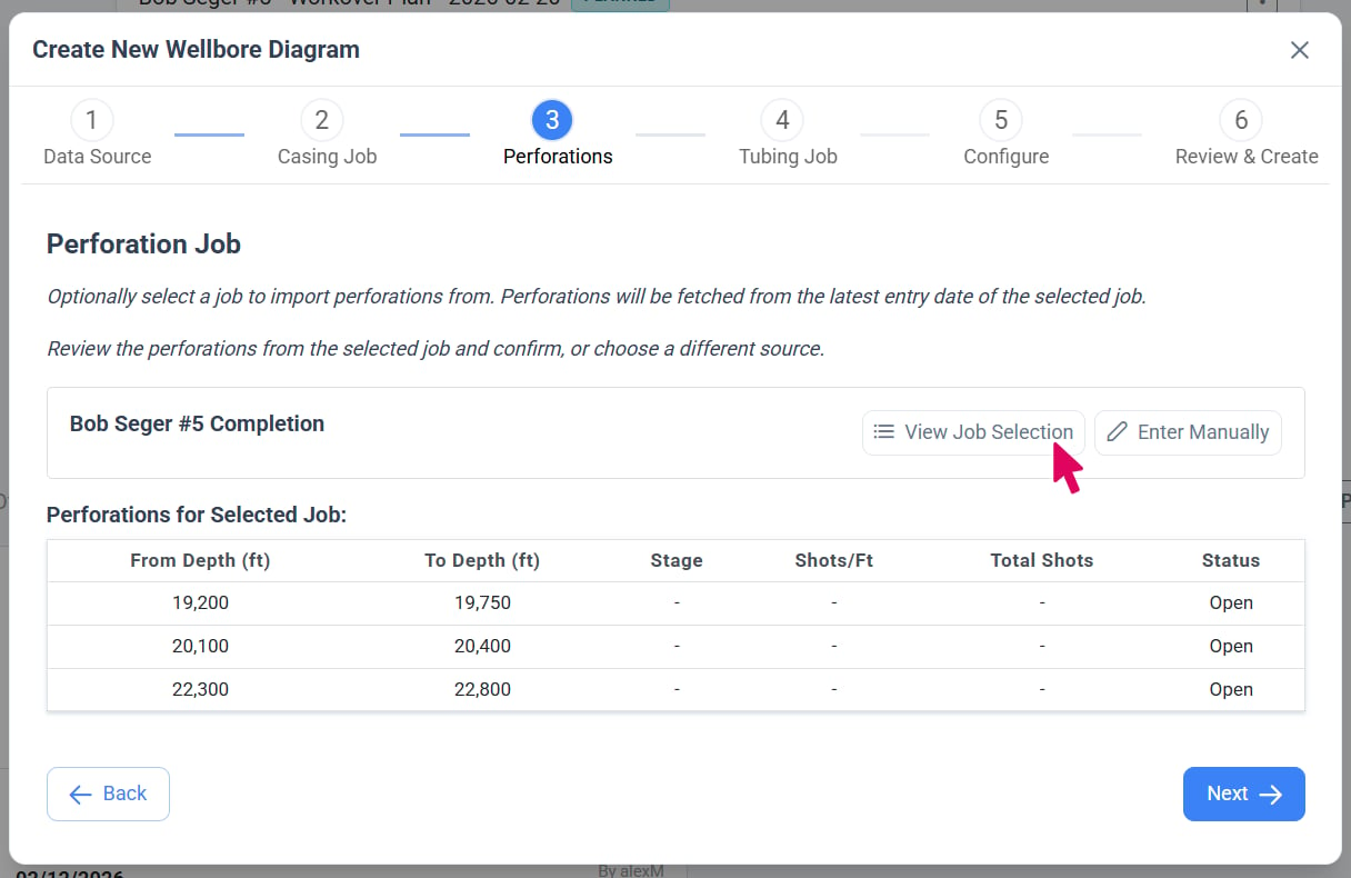
- View Job Selection - Click this button to open a table showing all available jobs with perforation data for this well. In the table, you can click Show next to any job to preview the perforation intervals associated with that job, or click Select to choose a job to import perforations from.
- Enter Manually - Click this button if you prefer to skip importing perforation data and enter it manually in the editor instead.
Select the Tubing Job
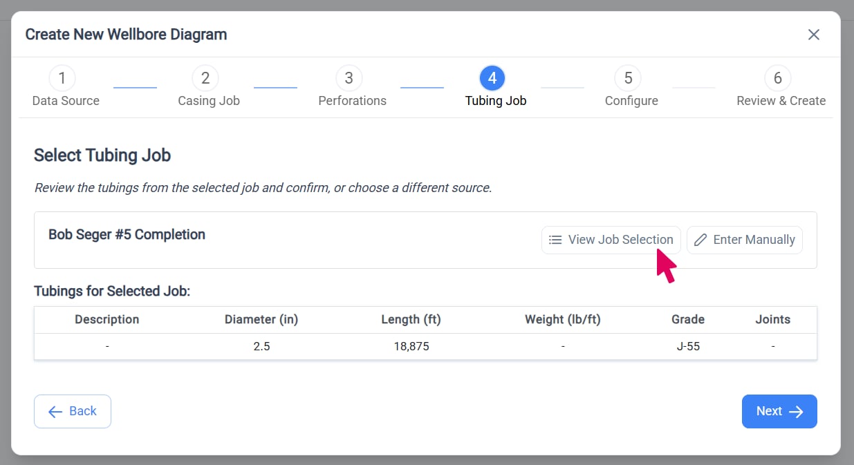
- View Job Selection - Click this button to open a table showing all available jobs with tubing IN data for this well. In the table, you can click Show next to any job to preview the tubing strings associated with that job, or click Select to choose a job to import tubing from.
- Enter Manually - Click this button if you prefer to skip importing tubing data and enter it manually in the editor instead.
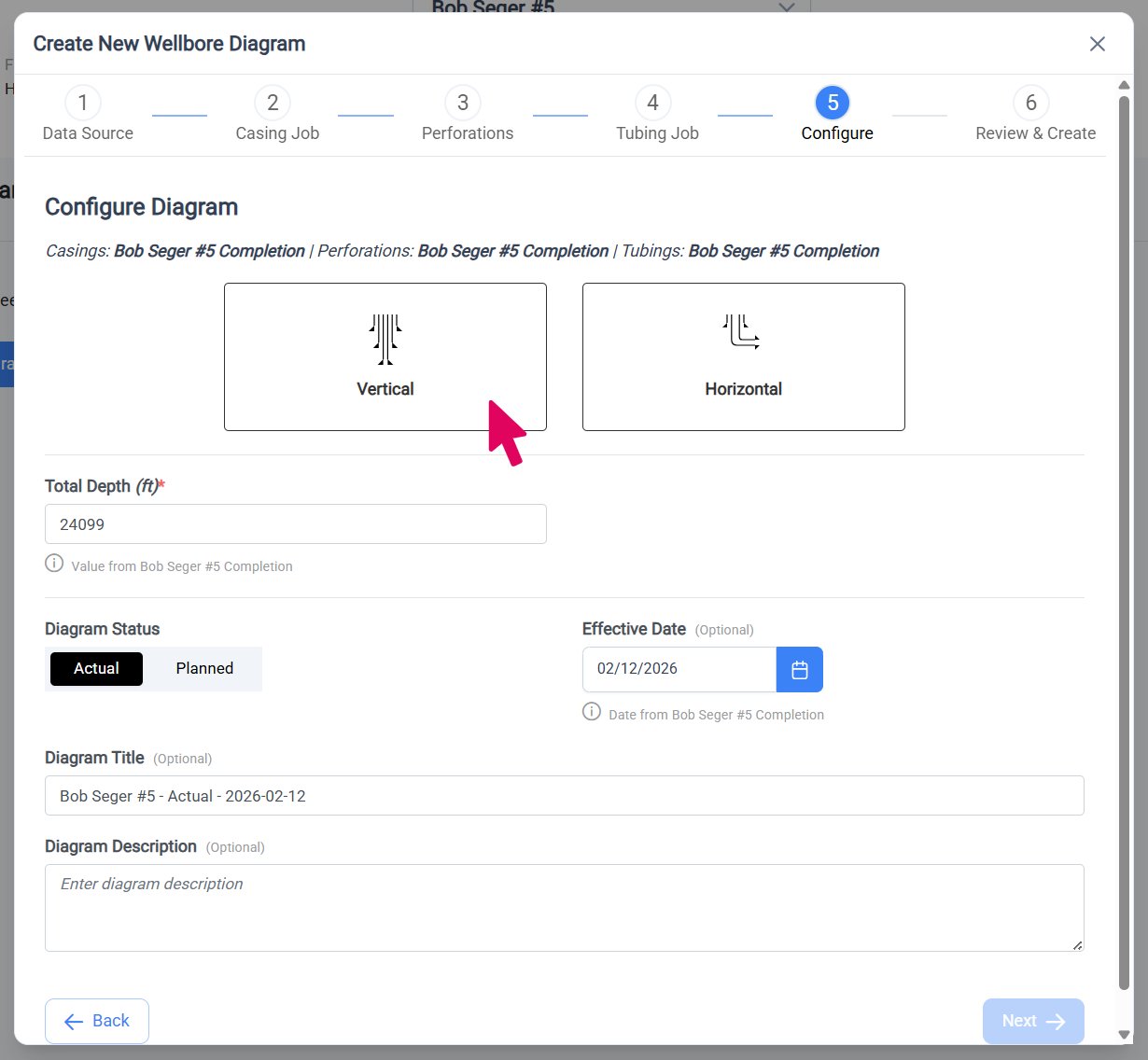
Well Type and Total Depth
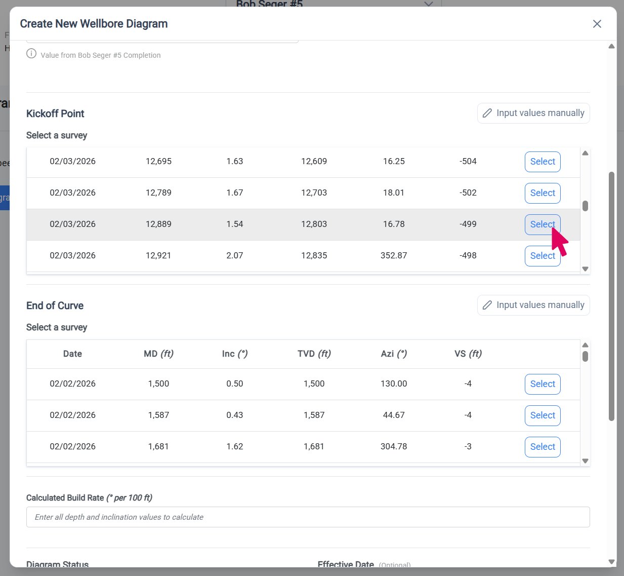
Horizontal Well Geometry
Complete Remaining Configuration
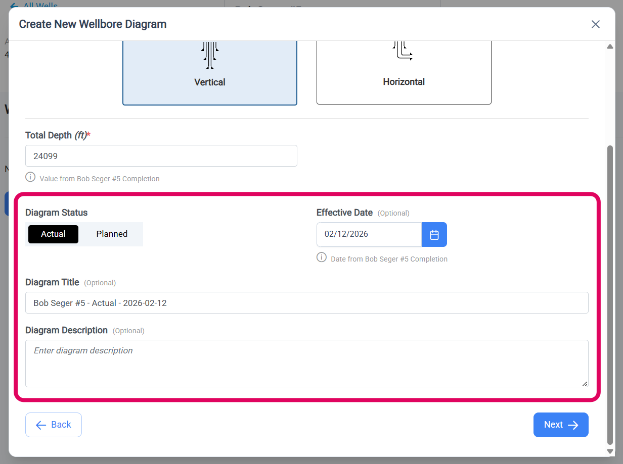
- Actual - This is used for actual (as drilled/completed) wellbore diagrams. You can note the date that the most recent changes were completed for the well.
- Planned - This is used to create planned wellbore diagrams for future drilling or completion changes. You can note the anticipated date of the drilling or changes to the well.
Review and Create Diagram
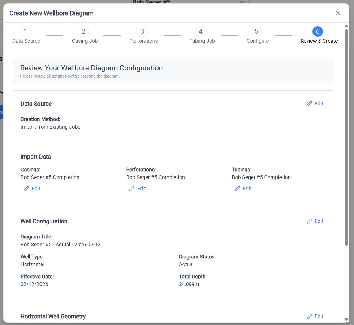
- Data source (existing jobs or from scratch)
- Imported jobs (if applicable): casing job, perforation job, tubing job
- Diagram configuration: well type, total depth, kickoff/end of curve, effective date
Wellbore Diagram Editor
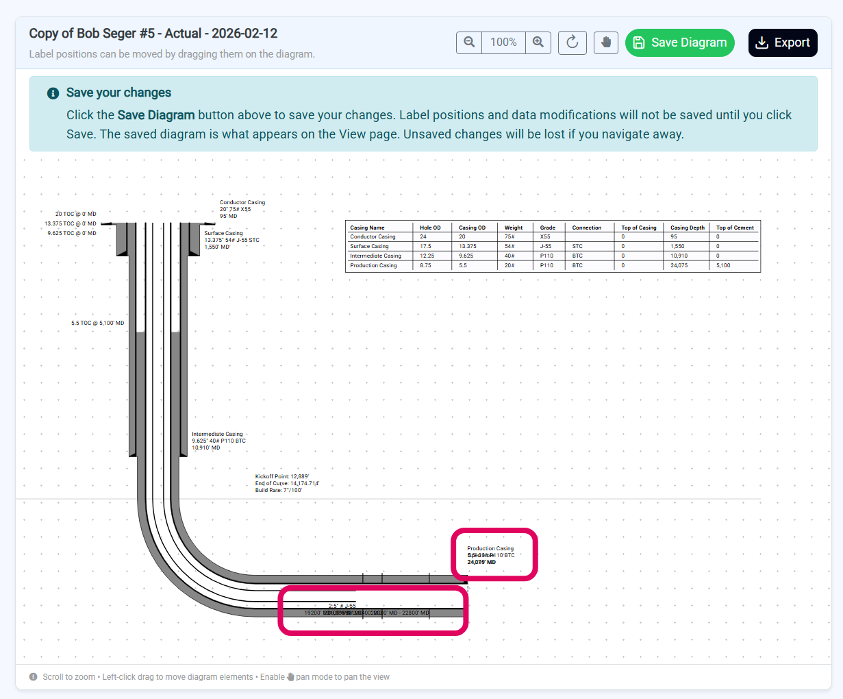
- Ensure Pan Mode is off (hand button in the header should be gray)
- Click and drag any label text or table to a new position
- Release to drop the label
Wellbore Diagram Viewer
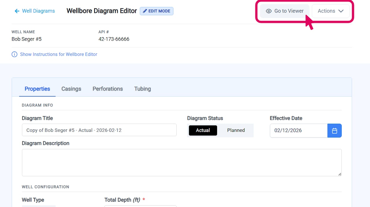
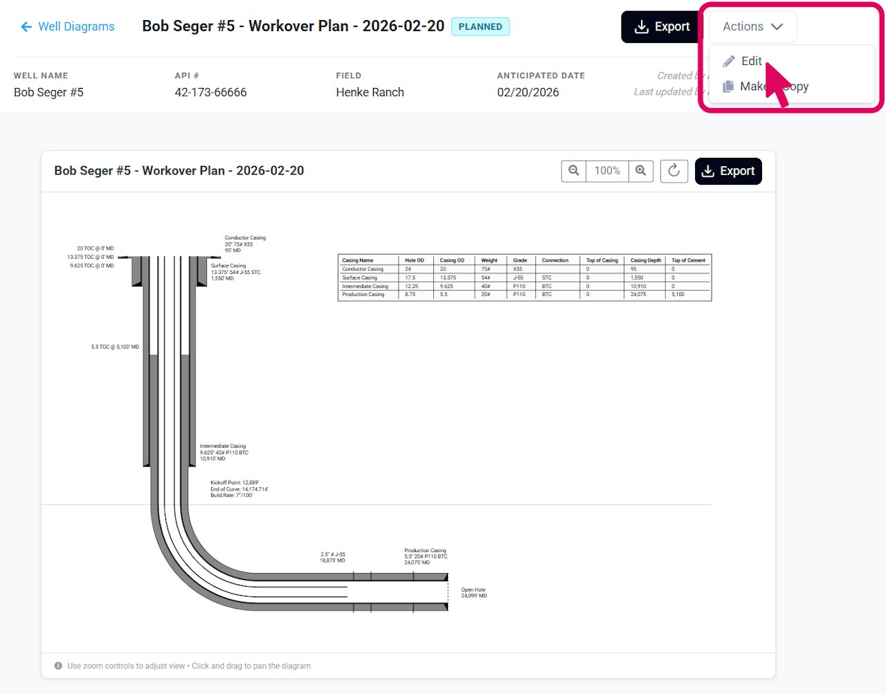
Edit Wellbore Diagram
Open the Wellbore Diagram Editor
Edit Diagram Properties
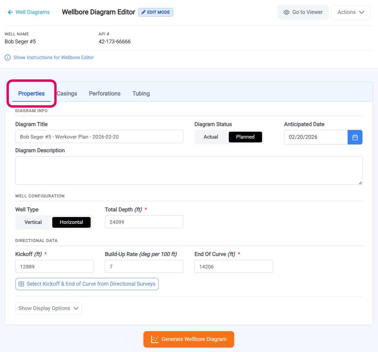
- Actual - This is used for actual (as drilled/completed) wellbore diagrams. You can note the date that the most recent changes were completed for the well.
- Planned - This is used for planned wellbore diagrams for future drilling or completion changes. You can note the anticipated date of the drilling or changes to the well.
Horizontal Well Geometry
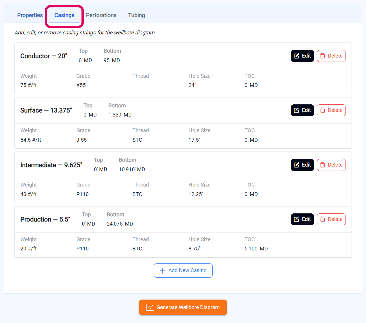
If your diagram’s well type is Horizontal, an additional Horizontal Well Geometry section will appear where you can update the kickoff point and end of curve values. If your well has directional surveys, click Select Kickoff & End of Curve from Directional Surveys. A table will display all directional surveys for the well. Review the survey data and click Select on the row that represents your kickoff point. Repeat this process for the end of curve survey. Build rate is calculated automatically when you click Apply Selections. If your well does not have directional surveys, you can enter the measured depth and inclination for the kickoff point and end of curve manually. Build rate is calculated automatically from your values. To switch from survey selection to manual entry, click Input Values Manually.Edit Casings
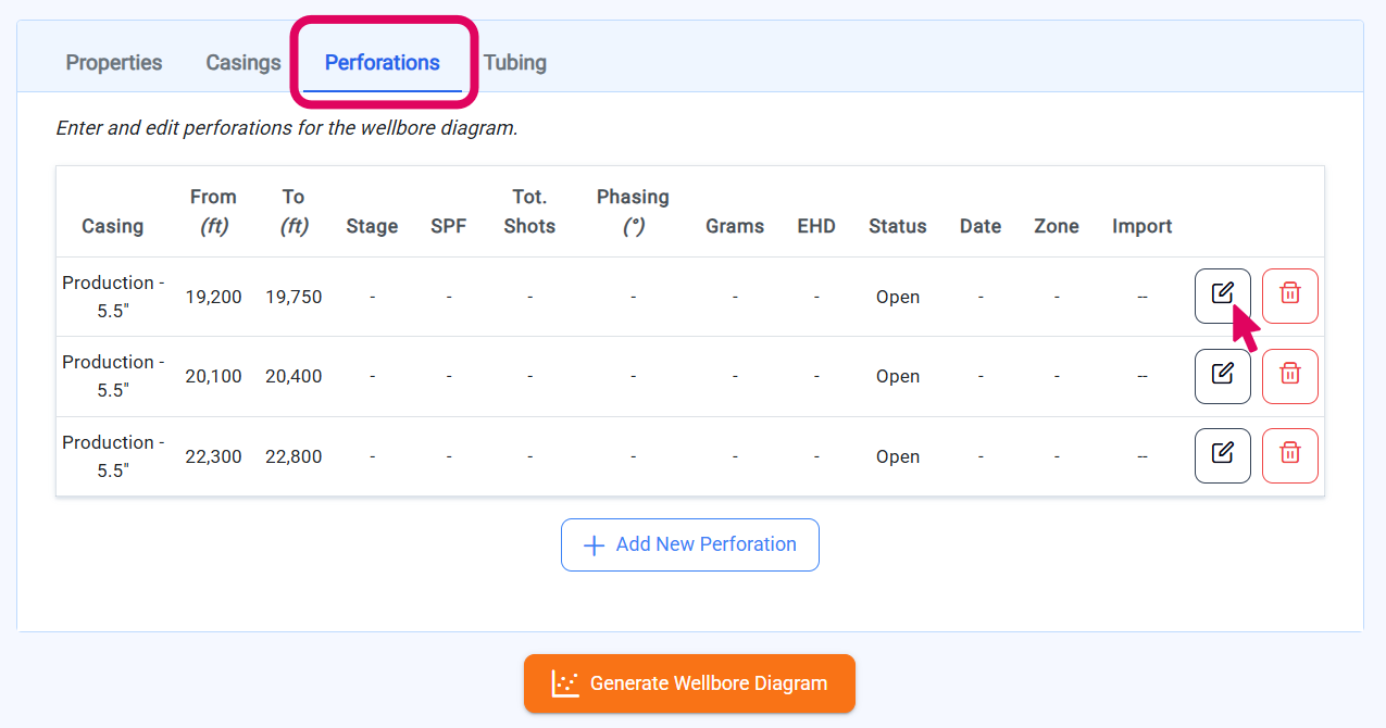
Edit Perforations
Edit Tubing
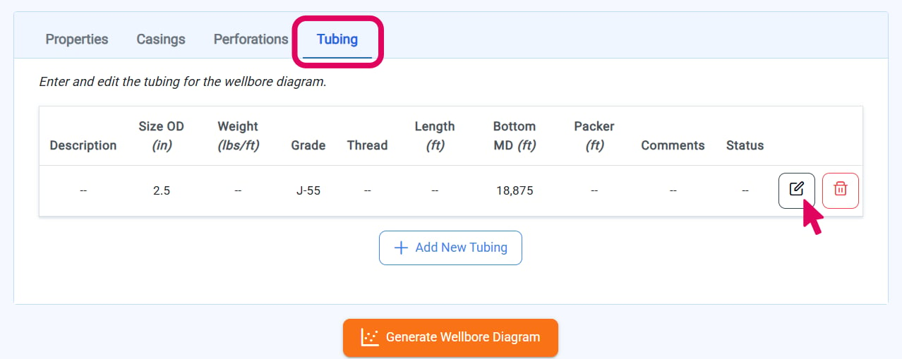
Generate Wellbore Diagram
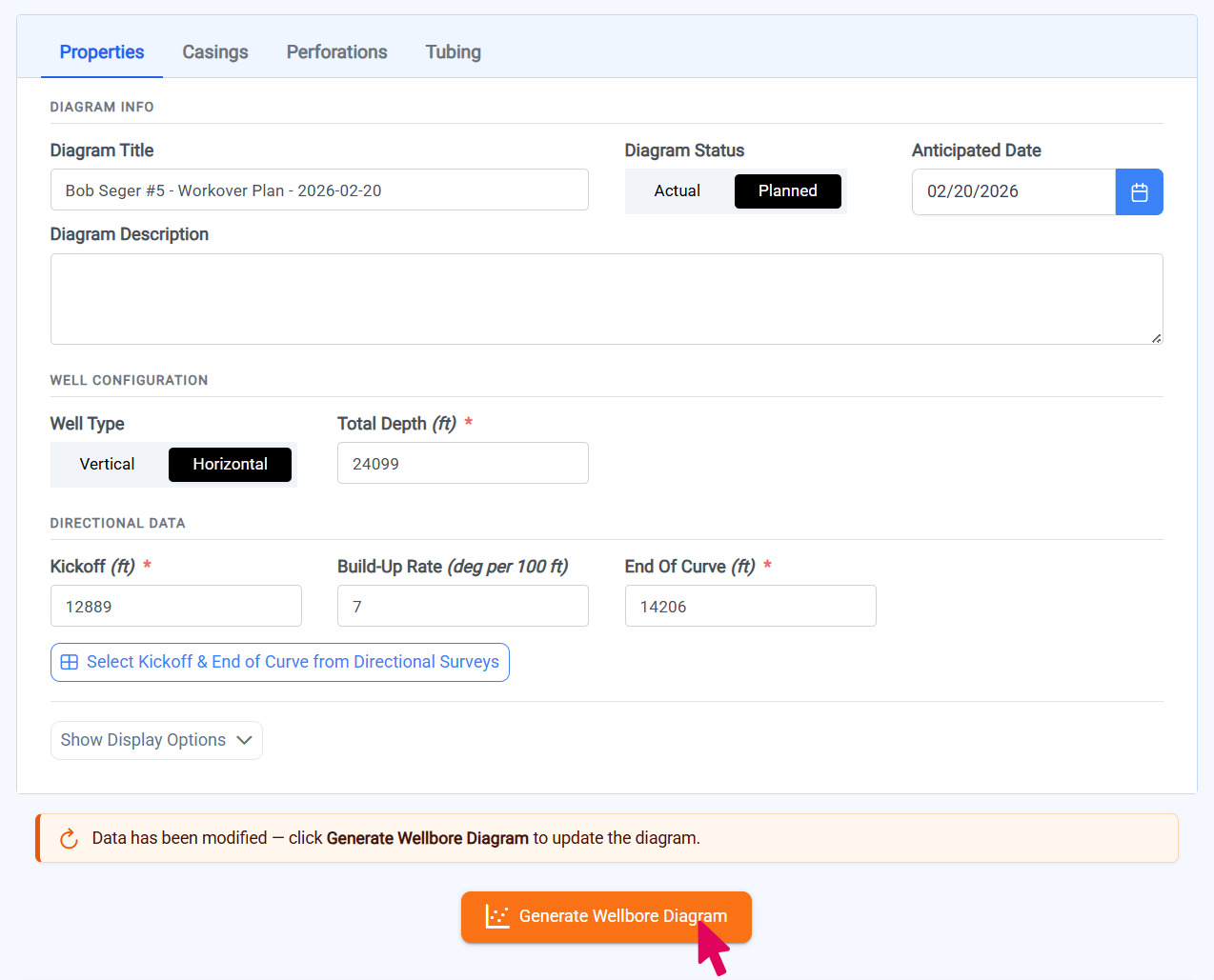
Preview and Reposition in Diagram Viewer
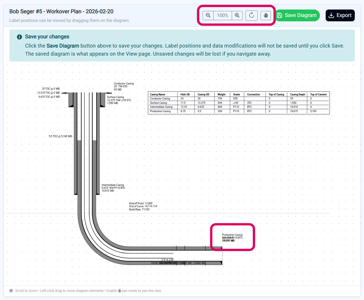
- Ensure Pan Mode is off (hand button should be gray)
- Click and drag any label text or table to a new position
- Release to drop the label
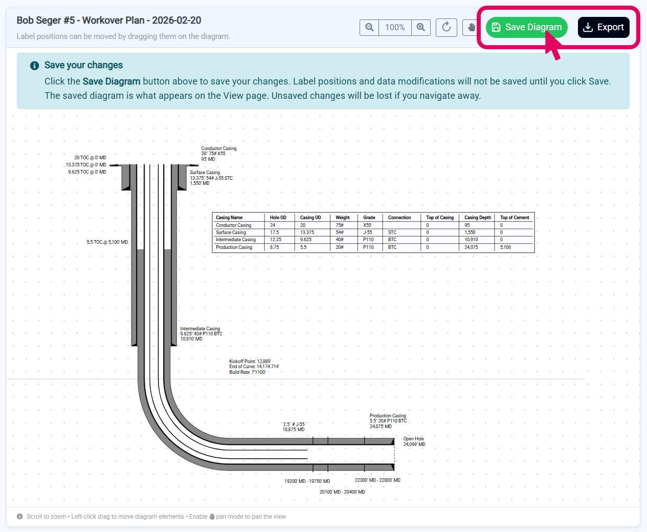
Save and Export Diagram
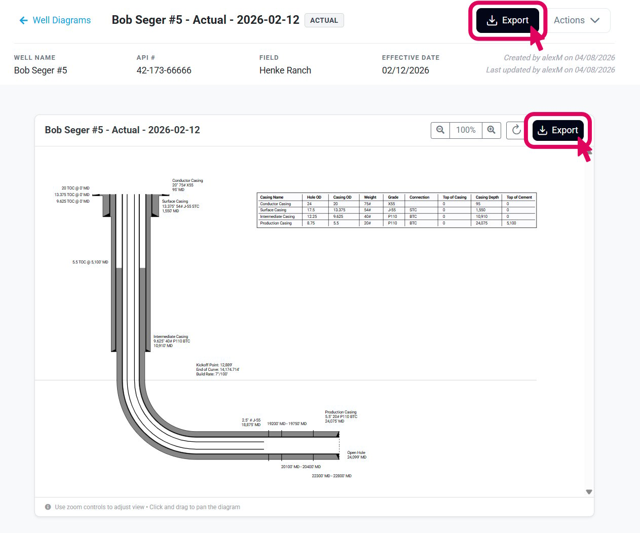
View Wellbore Diagram
Navigate to Wellbore Diagram List
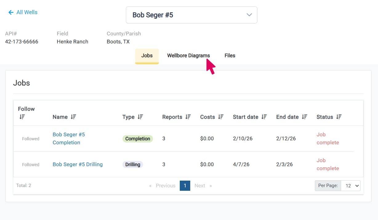
Select a Diagram
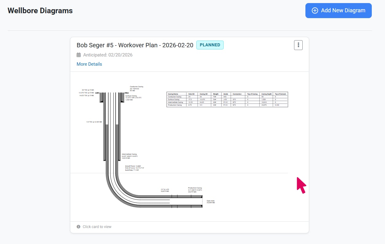
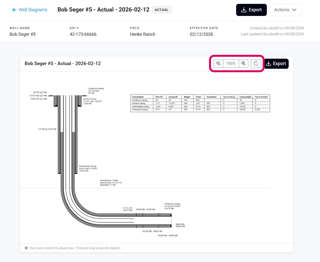
Use the Wellbore Diagram Viewer
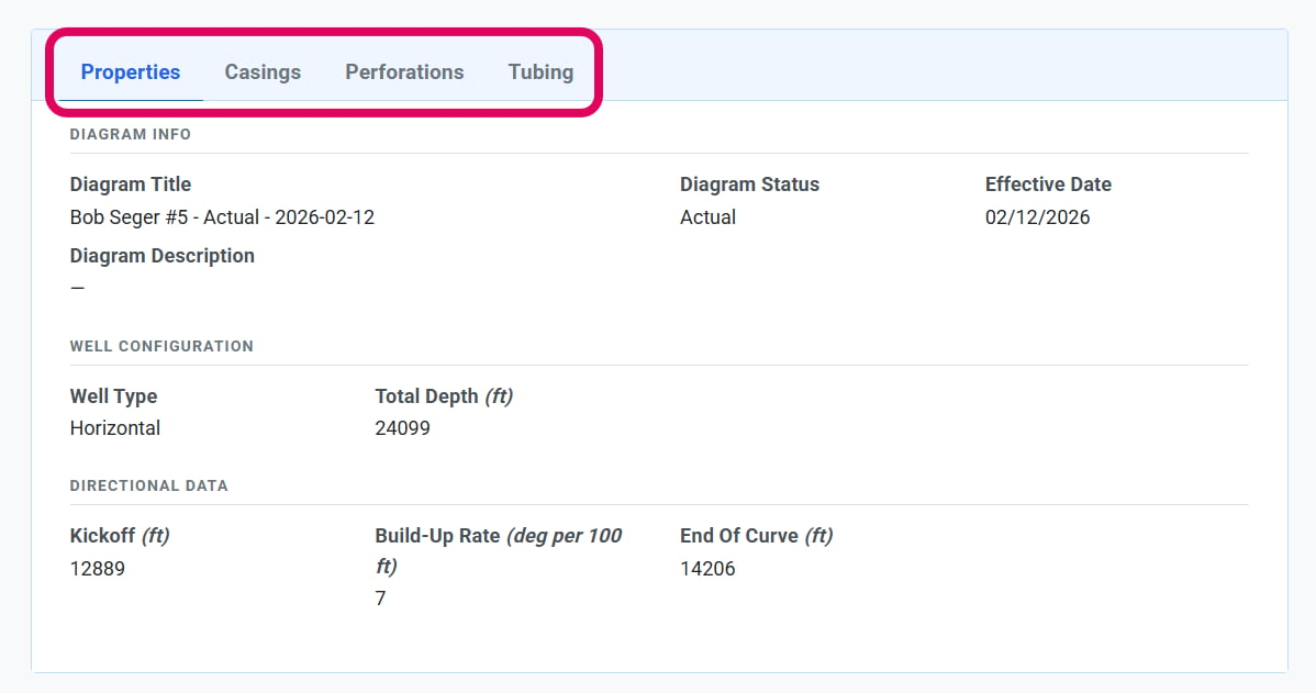
Review Design Specifications
Export Diagram
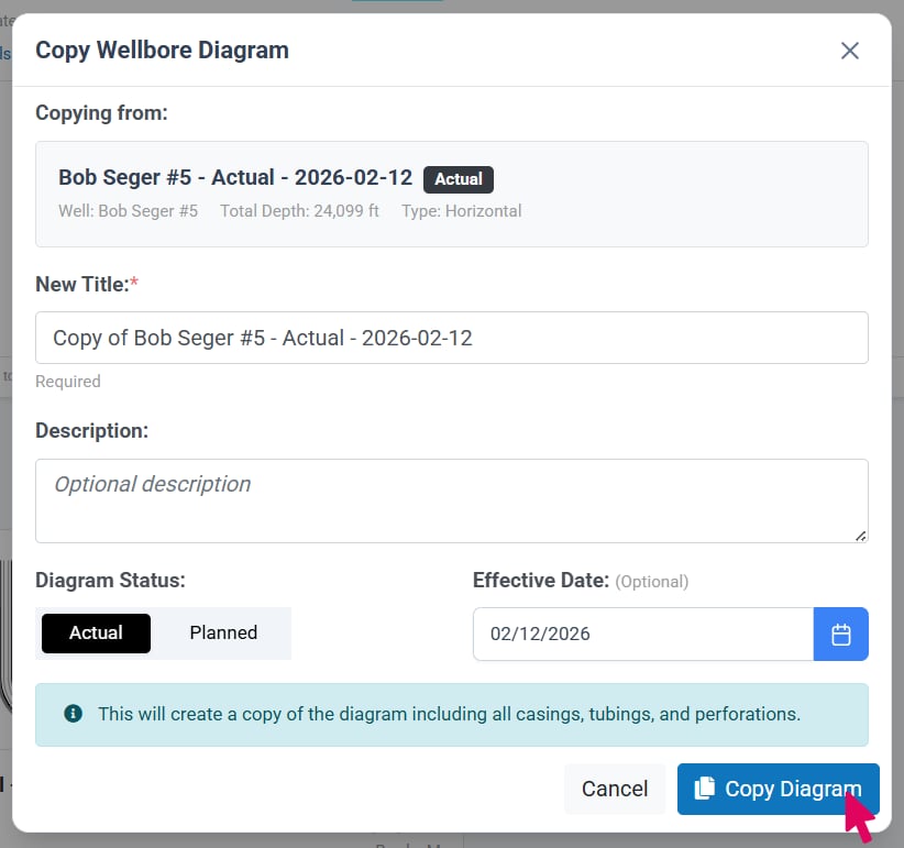
Copy Wellbore Diagram
Open the Copy Wellbore Diagram Window
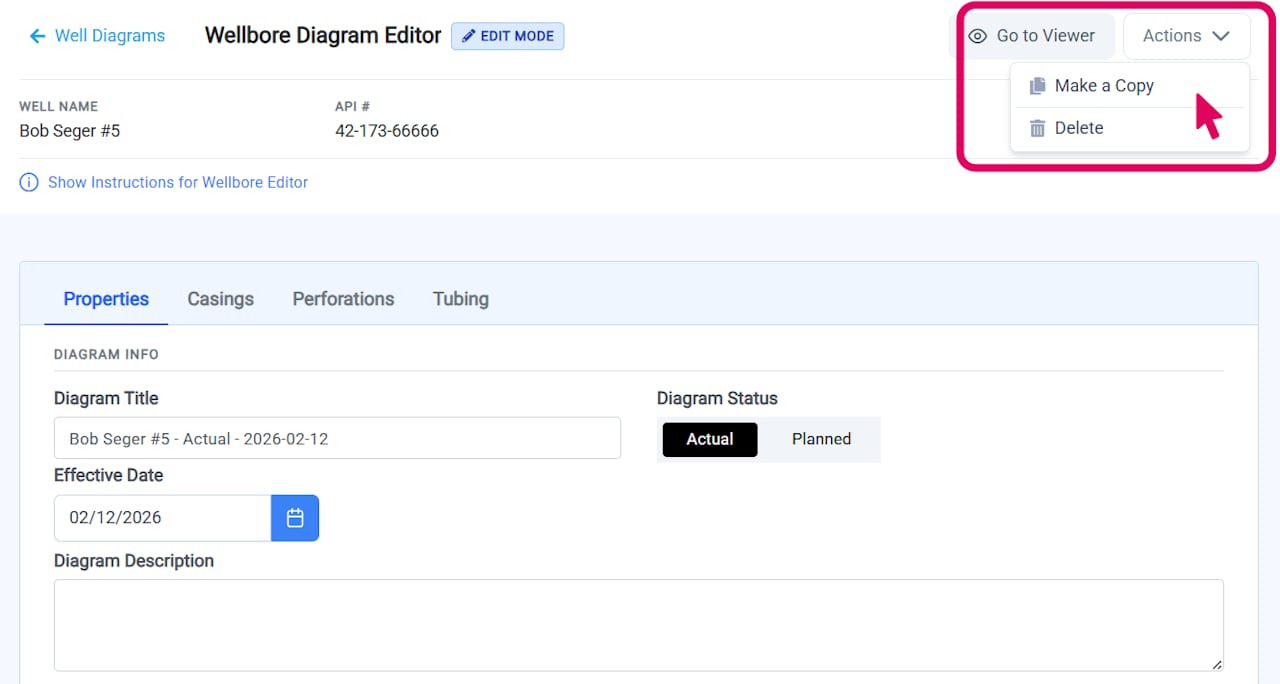
- From the list page - Click the three-dot menu button in the bottom right corner of any diagram card and select Make a Copy.
- From the editor - Click the three-dot menu button at the top of the editor and select Make a Copy.
- From the viewer - Click the three-dot menu button at the top of the viewer and select Make a Copy.
Review and Customize
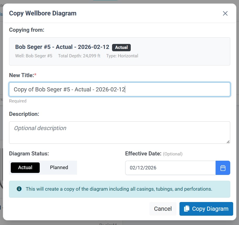
Create the Copy