> ## Documentation Index
> Fetch the complete documentation index at: https://docs.rigreports.com/llms.txt
> Use this file to discover all available pages before exploring further.
# Edit Wellbore Diagram
## Open the Wellbore Diagram Editor
**From Wellbore Diagram View Page**
From the wellbore diagram view page, click the **Actions** button in the header of the page. Then, select **Edit** from the dropdown menu.
 **From Wellbore Diagrams List**
On the well page, navigate to the wellbore diagram list. Then, locate the diagram you want to edit. Click the three-dot menu button of the diagram you want to edit and select **Edit Design** from the dropdown menu.
The editor will open and automatically load your saved diagram along with all design data and components.
**From Wellbore Diagrams List**
On the well page, navigate to the wellbore diagram list. Then, locate the diagram you want to edit. Click the three-dot menu button of the diagram you want to edit and select **Edit Design** from the dropdown menu.
The editor will open and automatically load your saved diagram along with all design data and components.
 ## Edit Diagram Properties
To modify diagram settings, click the **Properties** tab. You can make changes to any field:
1. Diagram Title, Description, Notes
2. Well Type (Vertical or Horizontal)
3. Total Depth (MD)
4. Effective/Anticipated Date
5. Planned or Actual status
6. Display Options
## Edit Diagram Properties
To modify diagram settings, click the **Properties** tab. You can make changes to any field:
1. Diagram Title, Description, Notes
2. Well Type (Vertical or Horizontal)
3. Total Depth (MD)
4. Effective/Anticipated Date
5. Planned or Actual status
6. Display Options
 All changes are saved automatically. After making changes to technical properties (depths, well type, display options), click **Generate Wellbore Diagram** to see the visual update.
Changes to basic information (title, description, notes, effective date, planned/actual status) don't require regenerating the diagram.
All changes are saved automatically. After making changes to technical properties (depths, well type, display options), click **Generate Wellbore Diagram** to see the visual update.
Changes to basic information (title, description, notes, effective date, planned/actual status) don't require regenerating the diagram.
 ### Horizontal Well Geometry — Horizontal Wells only
The **Directional Data** section only appears if you have selected a **Horizontal** diagram.
If your well is horizontal, you can set the Kickoff Point and End of Curve manually or use directional survey data for accuracy. Click **Select Kickoff & End of Curve from Directional Surveys** to open the survey selection modal. A table will display all directional surveys for the well. Review the survey data and click **Select** on the row that represents your kickoff point. Repeat this process for the end of curve survey. Once you have selected your kickoff and end of curve, your build rate will be automatically calculated. Click **Apply Selections** to save your changes.
### Horizontal Well Geometry — Horizontal Wells only
The **Directional Data** section only appears if you have selected a **Horizontal** diagram.
If your well is horizontal, you can set the Kickoff Point and End of Curve manually or use directional survey data for accuracy. Click **Select Kickoff & End of Curve from Directional Surveys** to open the survey selection modal. A table will display all directional surveys for the well. Review the survey data and click **Select** on the row that represents your kickoff point. Repeat this process for the end of curve survey. Once you have selected your kickoff and end of curve, your build rate will be automatically calculated. Click **Apply Selections** to save your changes.
 ## Edit Casings
To modify casing strings, click the **Casings** tab. Casings are displayed showing the casing type, outer diameter, and top and bottom depths.
Although **Hole Size** is not required, it is recommended you provide a value to insure the wellbore diagram renders properly.
## Edit Casings
To modify casing strings, click the **Casings** tab. Casings are displayed showing the casing type, outer diameter, and top and bottom depths.
Although **Hole Size** is not required, it is recommended you provide a value to insure the wellbore diagram renders properly.
 **To edit a casing:** Click **Edit** on the casing card. The edit modal opens with pre-filled values. Make your changes and click **Update Casing String**.
**To delete a casing:** Click **Delete** on the casing card. Confirm the deletion when prompted.
**To edit a casing:** Click **Edit** on the casing card. The edit modal opens with pre-filled values. Make your changes and click **Update Casing String**.
**To delete a casing:** Click **Delete** on the casing card. Confirm the deletion when prompted.
 **To add a casing:** Click **Add New Casing** at the bottom of the section. Fill in the required information and click **Add Casing String**.
After making changes, click **Generate Wellbore Diagram** to see visual updates.
**To add a casing:** Click **Add New Casing** at the bottom of the section. Fill in the required information and click **Add Casing String**.
After making changes, click **Generate Wellbore Diagram** to see visual updates.
 ## Edit Perforations
To modify perforations, click the **Perforations** tab. Perforations are displayed showing the associated casing, from/to depths, stage, shots per foot, and status.
## Edit Perforations
To modify perforations, click the **Perforations** tab. Perforations are displayed showing the associated casing, from/to depths, stage, shots per foot, and status.
 **To edit a perforation:** Click **Edit** in the table row. The edit modal opens with pre-filled values. Make your changes and click **Update Perforation**.
**To delete a perforation:** Click **Delete** in the table row. Confirm the deletion when prompted.
**To edit a perforation:** Click **Edit** in the table row. The edit modal opens with pre-filled values. Make your changes and click **Update Perforation**.
**To delete a perforation:** Click **Delete** in the table row. Confirm the deletion when prompted.
 **To add a perforation:** Click **Add New Perforation** at the bottom of the section. Fill in the required information including which casing the perforation is associated with, and click **Add Perforation**.
After making changes, click **Generate Wellbore Diagram** to see visual updates.
**To add a perforation:** Click **Add New Perforation** at the bottom of the section. Fill in the required information including which casing the perforation is associated with, and click **Add Perforation**.
After making changes, click **Generate Wellbore Diagram** to see visual updates.
 ## Edit Tubing
To modify tubing strings, click the **Tubing** tab. Tubing strings are displayed showing outer diameter, weight, depth, and description.
## Edit Tubing
To modify tubing strings, click the **Tubing** tab. Tubing strings are displayed showing outer diameter, weight, depth, and description.
 **To edit a tubing string:** Click **Edit** in the table row. The edit modal opens with pre-filled values. Make your changes and click **Update Tubing String**.
**To delete a tubing string:** Click **Delete** in the table row. Confirm the deletion when prompted.
**To edit a tubing string:** Click **Edit** in the table row. The edit modal opens with pre-filled values. Make your changes and click **Update Tubing String**.
**To delete a tubing string:** Click **Delete** in the table row. Confirm the deletion when prompted.
 **To add a tubing string:** Click **Add New Tubing** at the bottom of the section. Fill in the required information and click **Add Tubing**.
After making changes, click **Generate Wellbore Diagram** to see visual updates.
**To add a tubing string:** Click **Add New Tubing** at the bottom of the section. Fill in the required information and click **Add Tubing**.
After making changes, click **Generate Wellbore Diagram** to see visual updates.
 ## Generate Wellbore Diagram
After making changes to design data or components, a message will appear if the currently displayed diagram does not reflect the applied changes. To generate a new diagram with the changes, click **Generate Wellbore Diagram**.
The displayed wellbore diagram will not reflect your changes until you regenerate the diagram.
## Generate Wellbore Diagram
After making changes to design data or components, a message will appear if the currently displayed diagram does not reflect the applied changes. To generate a new diagram with the changes, click **Generate Wellbore Diagram**.
The displayed wellbore diagram will not reflect your changes until you regenerate the diagram.
 If you have repositioned labels on your current diagram and have not saved it, a confirmation window will warn you that regenerating will reset all label positions. Click **Generate Wellbore Diagram** to confirm and proceed.
Label positions are reset when you regenerate a diagram. After the diagram has generated, you can reposition your labels before saving.
If you have repositioned labels on your current diagram and have not saved it, a confirmation window will warn you that regenerating will reset all label positions. Click **Generate Wellbore Diagram** to confirm and proceed.
Label positions are reset when you regenerate a diagram. After the diagram has generated, you can reposition your labels before saving.
 ## Diagram Viewer
After generating your diagram, you can preview it, edit label positions, and save it in the diagram viewer.
**Zoom Controls** — Use the zoom dropdown at the top to zoom in or out.
**Fit to Window** — Click the reset button to reset the zoom to 100% and center the diagram.
## Diagram Viewer
After generating your diagram, you can preview it, edit label positions, and save it in the diagram viewer.
**Zoom Controls** — Use the zoom dropdown at the top to zoom in or out.
**Fit to Window** — Click the reset button to reset the zoom to 100% and center the diagram.
 **Toggle Pan and Edit** — Click the hand button to toggle between **Pan** and **Edit** modes.
* In **Pan** mode, the hand button will be blue and you can click and drag to move the entire diagram.
* In **Edit** mode, the hand will be gray and clicking and dragging will reposition diagram elements.
**To reposition labels:**
1. Ensure **Pan Mode** is off (hand button should be gray)
2. Click and drag any label text or table to a new position
3. Release to drop the label
When you move a label, the **Save Diagram** button becomes enabled, indicating there are unsaved visual changes.
Remember to click **Save Diagram** to save your generated diagram with any label repositioning for the Viewer. If you do not save your changes, the Viewer page will not display the updated diagram.
**Toggle Pan and Edit** — Click the hand button to toggle between **Pan** and **Edit** modes.
* In **Pan** mode, the hand button will be blue and you can click and drag to move the entire diagram.
* In **Edit** mode, the hand will be gray and clicking and dragging will reposition diagram elements.
**To reposition labels:**
1. Ensure **Pan Mode** is off (hand button should be gray)
2. Click and drag any label text or table to a new position
3. Release to drop the label
When you move a label, the **Save Diagram** button becomes enabled, indicating there are unsaved visual changes.
Remember to click **Save Diagram** to save your generated diagram with any label repositioning for the Viewer. If you do not save your changes, the Viewer page will not display the updated diagram.
 ## Save and Export Diagram
**Save Diagram**
Once you're satisfied with your diagram and label positions, click **Save Diagram** above the diagram display area.
## Save and Export Diagram
**Save Diagram**
Once you're satisfied with your diagram and label positions, click **Save Diagram** above the diagram display area.
 If a version of the diagram has been previously saved, you will be asked to confirm that you want to overwrite it. Click **Overwrite** to confirm. The diagram is saved to storage and immediately available in the viewer and on the list page.
After the diagram has been saved, the **Save Diagram** button becomes disabled, indicating no unsaved changes.
If a version of the diagram has been previously saved, you will be asked to confirm that you want to overwrite it. Click **Overwrite** to confirm. The diagram is saved to storage and immediately available in the viewer and on the list page.
After the diagram has been saved, the **Save Diagram** button becomes disabled, indicating no unsaved changes.
 **Export Diagram**
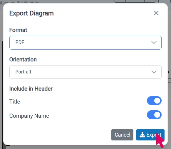
Click the **Export** button to open the export options. Use the **Format** dropdown to select the format you would like your exported file to be. If you choose to export as a PDF, you can then select the **Orientation** and the data **Included in the Header** for your document. Once you have selected your desired settings, click **Export** to export the wellbore diagram.
**Export Diagram**
Click the **Export** button to open the export options. Use the **Format** dropdown to select the format you would like your exported file to be. If you choose to export as a PDF, you can then select the **Orientation** and the data **Included in the Header** for your document. Once you have selected your desired settings, click **Export** to export the wellbore diagram.